TrossPlan · Worked example
Prepare a measured model-rigging work pack
A drawing tells you where a line goes. A measured run tells you how much line to prepare. This example keeps those two facts separate while putting them into one printable work pack.
By Perunlight · AI-assisted. Original demonstration files; sample results independently checked against the downloadable files. Published .
Read the small fictional Mira layout
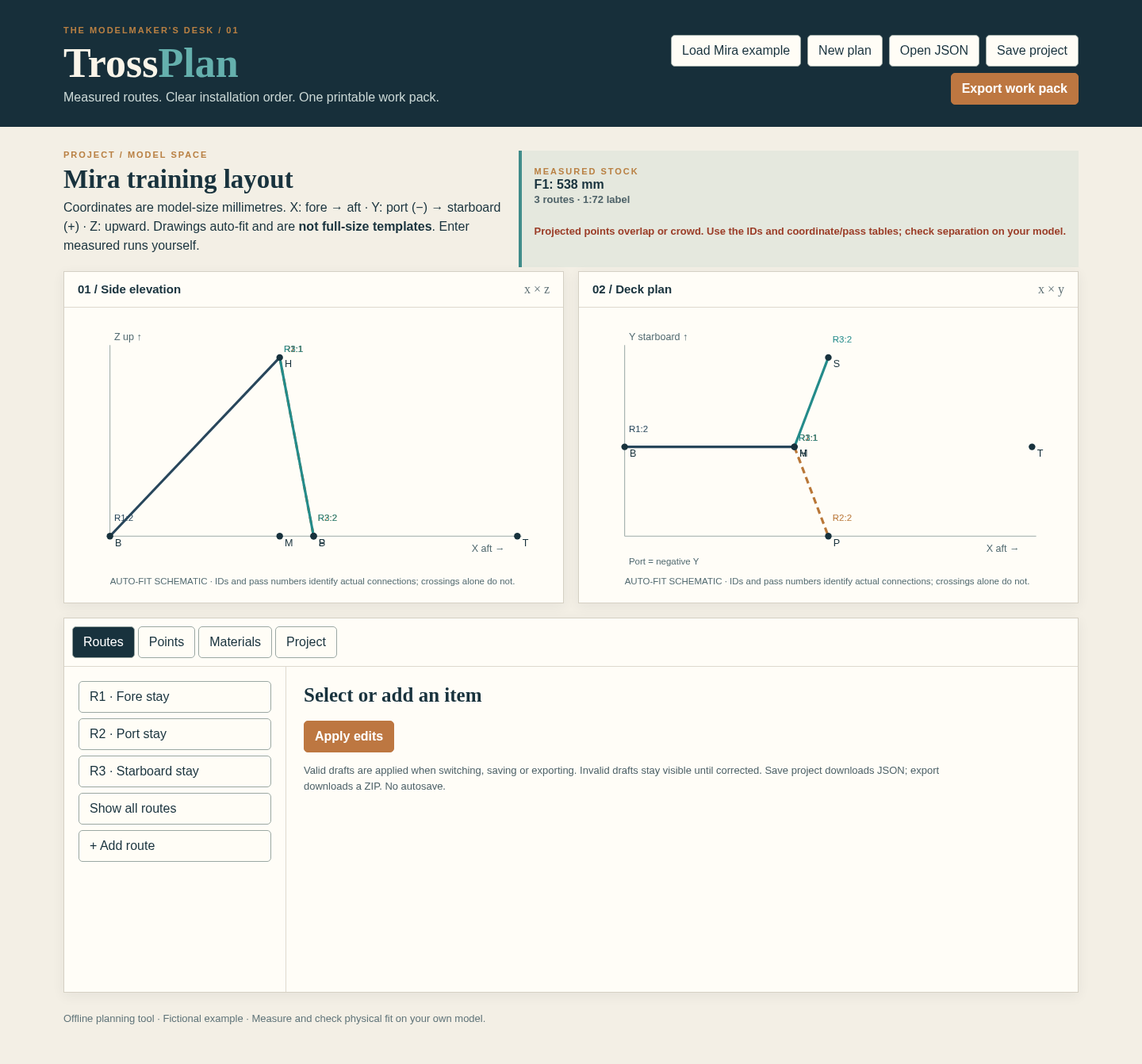
The free Mira pack is a six-point, one-mast training example labelled 1:72. It is not a plan for a real vessel. Its coordinates are already model-size millimetres; the scale label does not rescale them.
Point  x    y    z (mm)
B      0    0    0      bow eye
M    100    0    0      mast base
H    100    0  150      masthead
P    120  -25    0      port chainplate
S    120   25    0      starboard chainplate
T    240    0    0      stern eye
The side view uses x and z; the top view uses x and y. The negative y coordinate keeps the port chainplate on its own side. Both drawings are fitted schematics, not full-size cutting templates.
Write the route and its measured quantity
R1 runs from H to B. R2 runs from H to P and R3 from H to S. The sample declares that R2 and R3 follow R1. These requirements express the author’s chosen sequence; they do not prove that a real model can be assembled in that order.
Route   Entered run + allowance = total
R1          181 mm + 15 mm     = 196 mm
R2          156 mm + 15 mm     = 171 mm
R3          156 mm + 15 mm     = 171 mm

One sample thread family: 538 mm = 0.538 m
The 0.25 mm thread family and entered lengths are illustrative. Measure your own model and choose allowances for the actual route and fastening method. TrossPlan adds entered quantities; it does not turn straight-line drawing distances into reliable cutting lengths.
Change one allowance and check the result
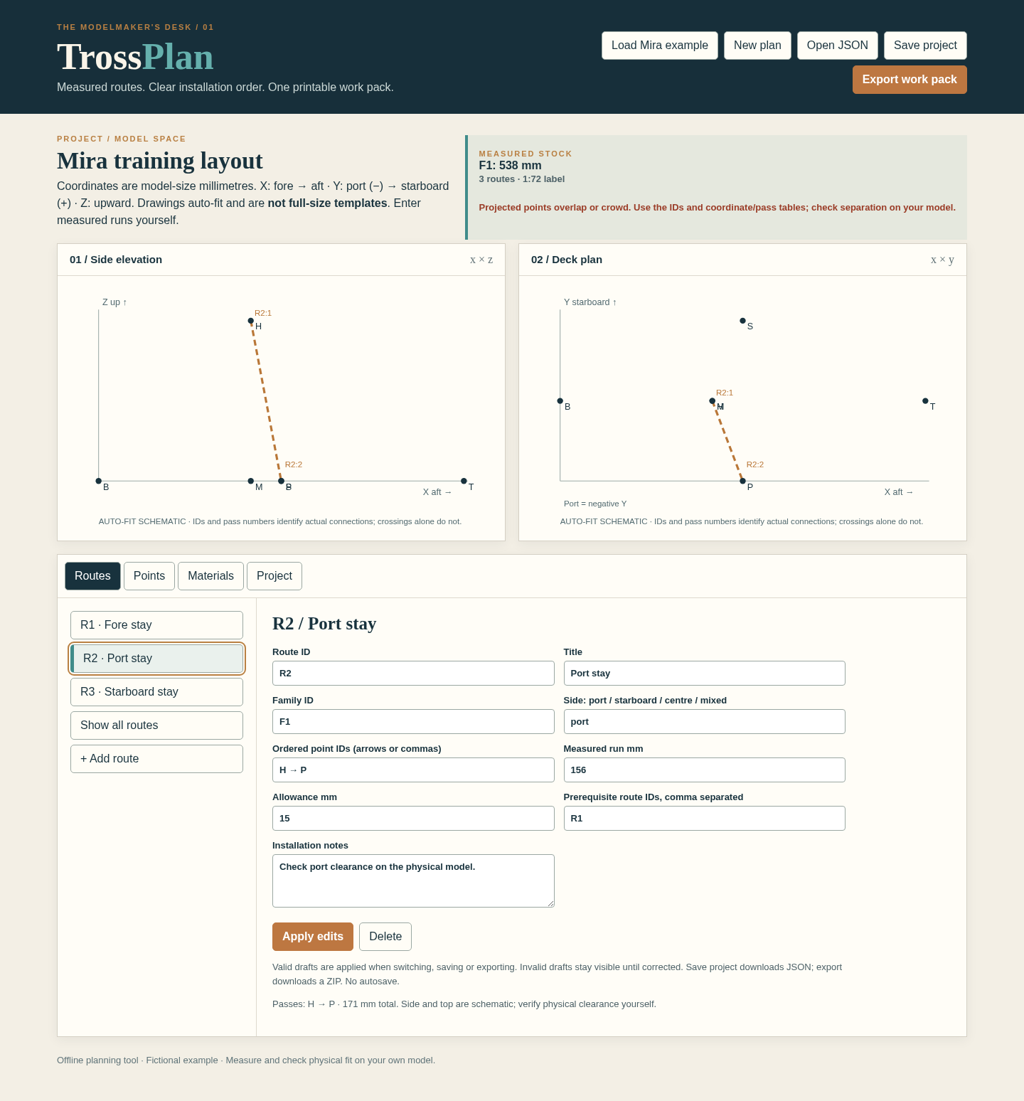
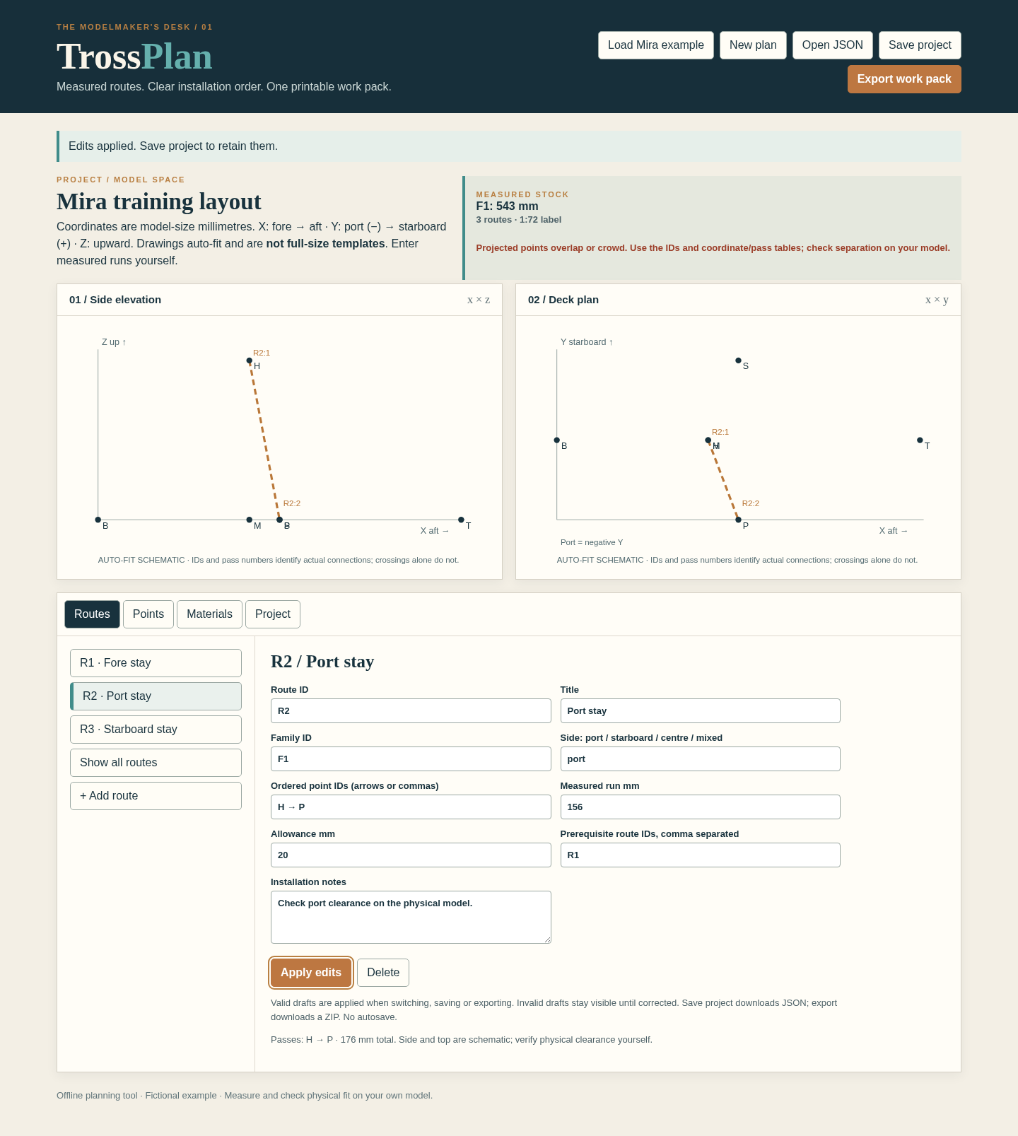
Save the original project, then change only R2 allowance from 15 mm to 20 mm and choose Apply edits. Its entered run remains 156 mm, so R2 becomes 176 mm. R1 and R3 remain 196 mm and 171 mm.
Updated family total = 196 + 176 + 171 = 543 mm
543 mm = 0.543 m
Difference from the original pack = 5 mm
The allowance is a quantity field. Changing it should update the route card and material schedule without moving an attachment point or changing either drawing.
Take the same project to the bench
- Inspect both SVG views and the point IDs before using the diagrams.
- Read the ordered point list on each route card; a drawn crossing is not a connection.
- Check the measured run, allowance and family on the route card.
- Compare route and family totals in the PDF and CSV files.
- Keep the saved project JSON so later edits start from the same data.
Repeated passes through a point can be intentional. Crowded or coincident projections need review against the written route and coordinate table. The diagram alone cannot verify clearance, knot size or a historically correct rig.
Choose A4 or US Letter in the project and inspect the downloaded PDF. An invalid dependency cycle needs an explicit correction before export; the editable project should remain available while you fix it.
Recalculate the example independently
You can reproduce the quantities with the three additions shown above, without drawing software. The original family total is 538 mm. Increasing only R2 allowance by 5 mm makes the total 543 mm and leaves the coordinates unchanged.
Expected change: R2 total 171 → 176 mm; family total 538 → 543 mm. Route geometry and the other two quantities stay unchanged.
The example checks digital authoring, output consistency and arithmetic. No physical rigging build, material adequacy or historical-accuracy claim is made.
Perunlight product
Make a work pack for your own project
Turn named attachment points and measured routes into side and top diagrams, installation cards and a material schedule.
TrossPlan · $19 onceRead the illustrated guide
The free pack contains original example files and a quick start. It does not contain the paid editor. The editor is a downloadable offline app; desktop Chrome on Linux is the tested environment.